


What is an Octagonal Tube Gripper?
An octagonal tube gripper is a fixture designed for industrial automation lines, enabling robots to automatically grip and handle workpieces. The gripper’s main structure is made of octagonal aluminum alloy tubes, available in various sizes with evenly spaced mounting holes. The tubes are assembled using blind rivet nuts and connectors, allowing gripping units to be installed at multiple angles and positions. This flexibility allows them to handle workpieces of various shapes and sizes, streamlining the design process and enhancing production efficiency.
Measurement Challenges
Despite the clear advantages of octagonal tube grippers, what challenges arise during the pre-assembly and re-measurement processes?
1. Human Assembly Errors
Octagonal tubes are uniform in shape, and during assembly, the connector positioning depends on manually calculated hole placements. This human-driven process can lead to misaligned holes, preventing proper grip and accurate workpiece handling.
2. Force Majeure
The sequence in which screws are tightened can cause slight, uncontrollable rotations between connected tubes, affecting the gripper’s ability to maintain precise alignment and grip on the workpieces.
3. Gravity-Induced Deformation
For larger parts (e.g., automotive side panels), the gripper may exceed 2 meters in length. During robotic movement and angle adjustments, gravity can cause deformation, impacting the gripping accuracy.
Measurement Solution with PMT Portable Measuring Arm
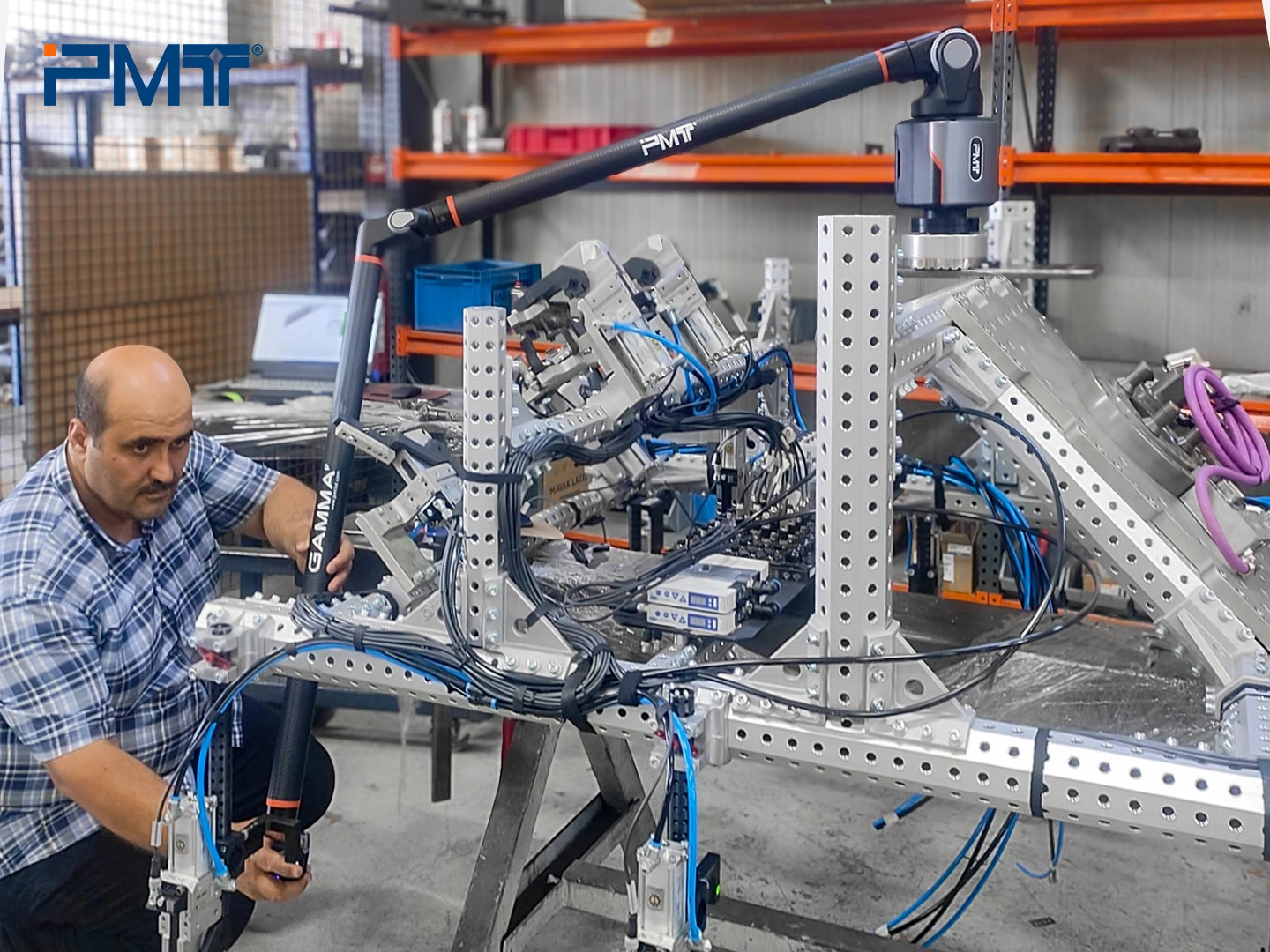
To tackle the challenges mentioned above, the portable measuring arm provides an ideal solution, offering portability and high efficiency for both the assembly and inspection processes of octagonal tube grippers. This case study highlights how a leading automation solutions provider in Turkey used the PMT portable measuring arm to solve critical production issues, enhancing accuracy and efficiency in their manufacturing process.
A. Measurement Solution for the Assembly Process
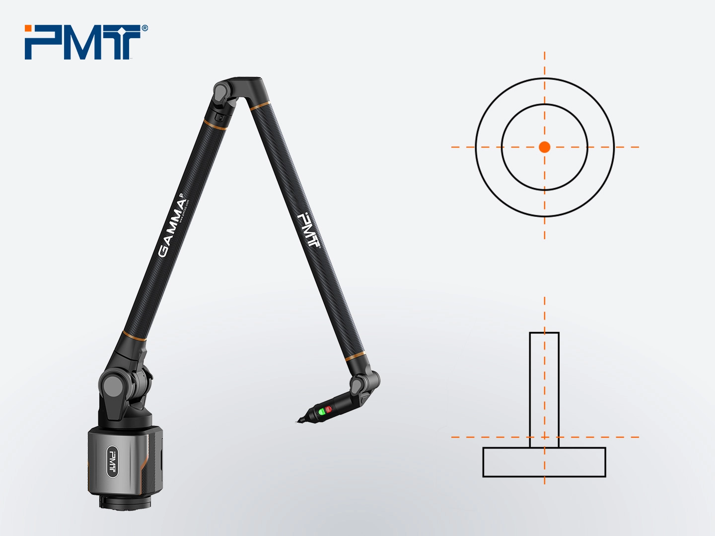
The PMT measuring arm enables real-time inspection of the concentricity and perpendicularity between the gripper and robot flange, as well as the parallelism and perpendicularity between tubes. This helps detect and prevent failures caused by accumulated errors.
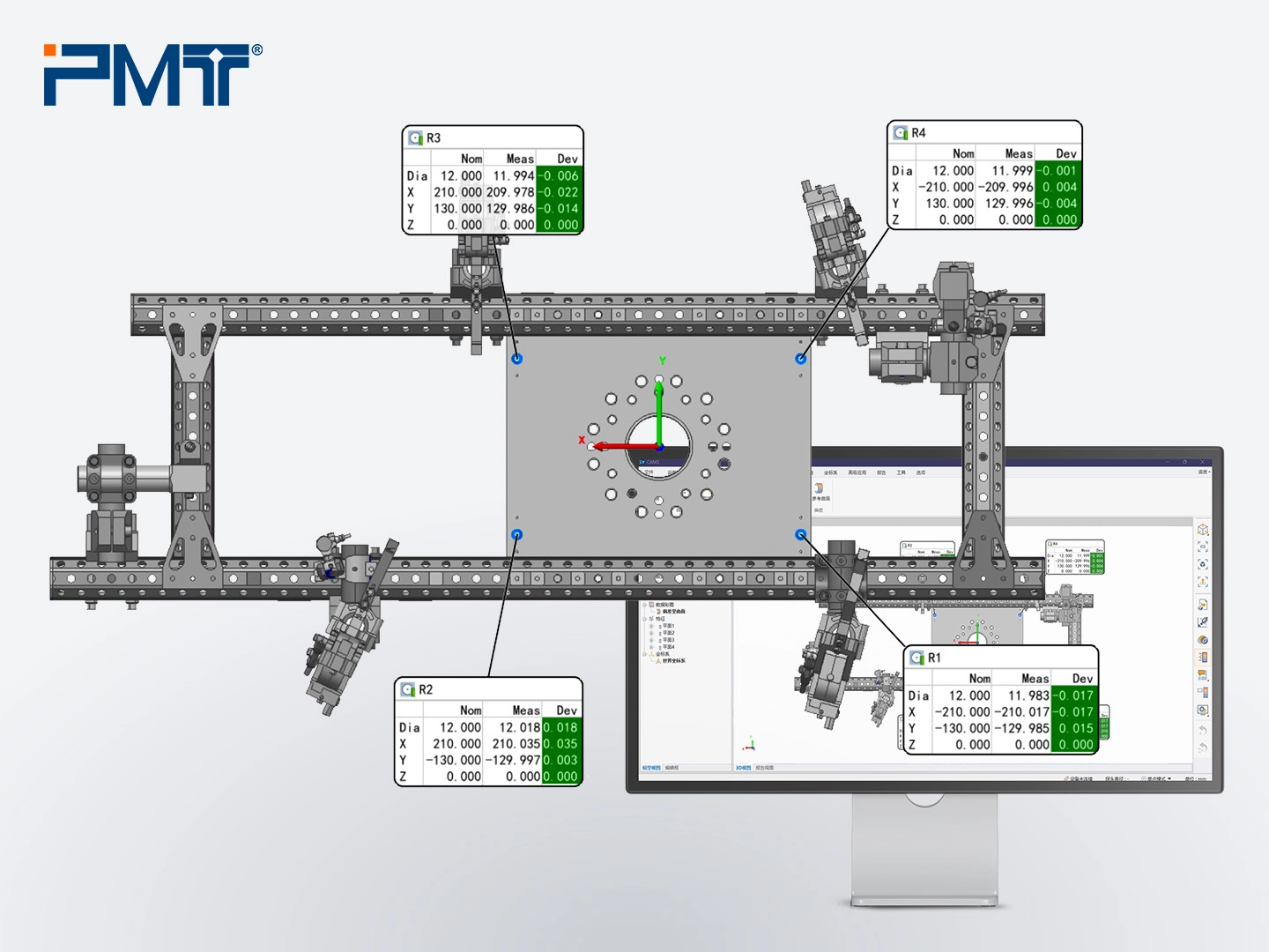
By aligning the pinholes on the connecting plate with the CAD model, misaligned holes in the assembly can be quickly detected and corrected, ensuring rapid response and maintaining assembly accuracy.
Measurement Steps
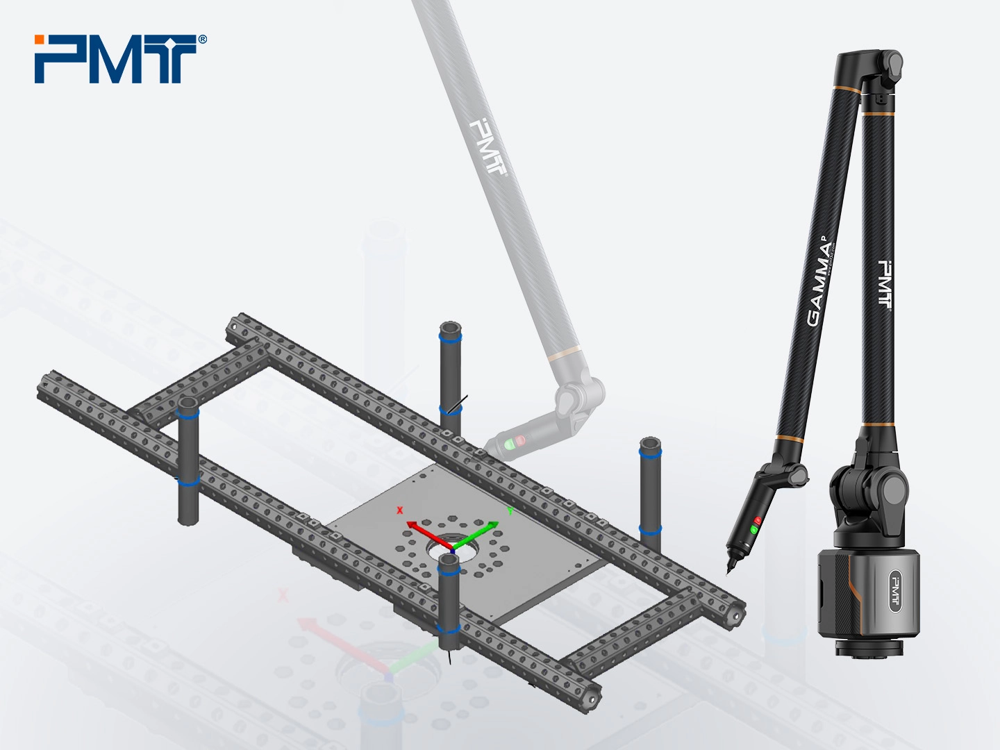
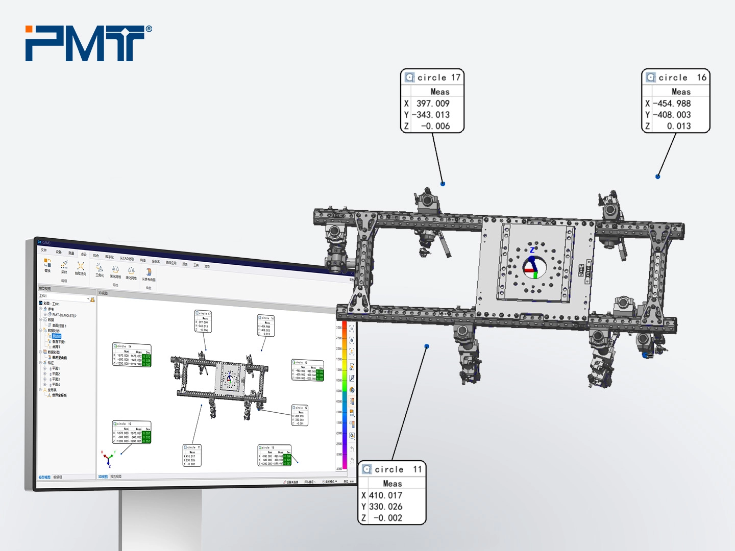
1. Use the portable measuring arm’s probe to contact the reference holes on the connector plate, then apply Best-Fit to align the gripper with the CAD model in 3D measurement software.
2. Measure the connector plate plane and define it as Datum A. Then measure the main frame plane and the cylindrical vertical tubes of other grippers to assess parallelism and perpendicularity.
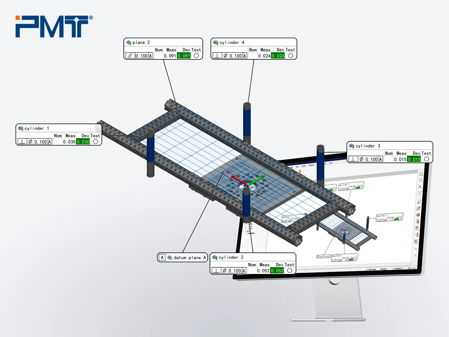
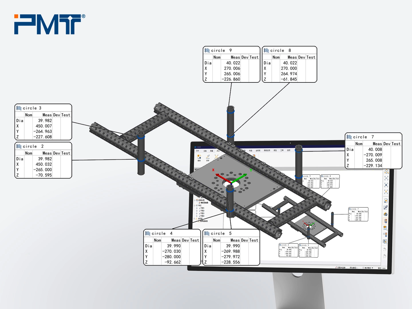
3. If deviations exceed tolerance, construct features (e.g., circles on cylindrical tubes) and compare XY coordinates at different heights to calculate required adjustments. This step ensures assembly accuracy.
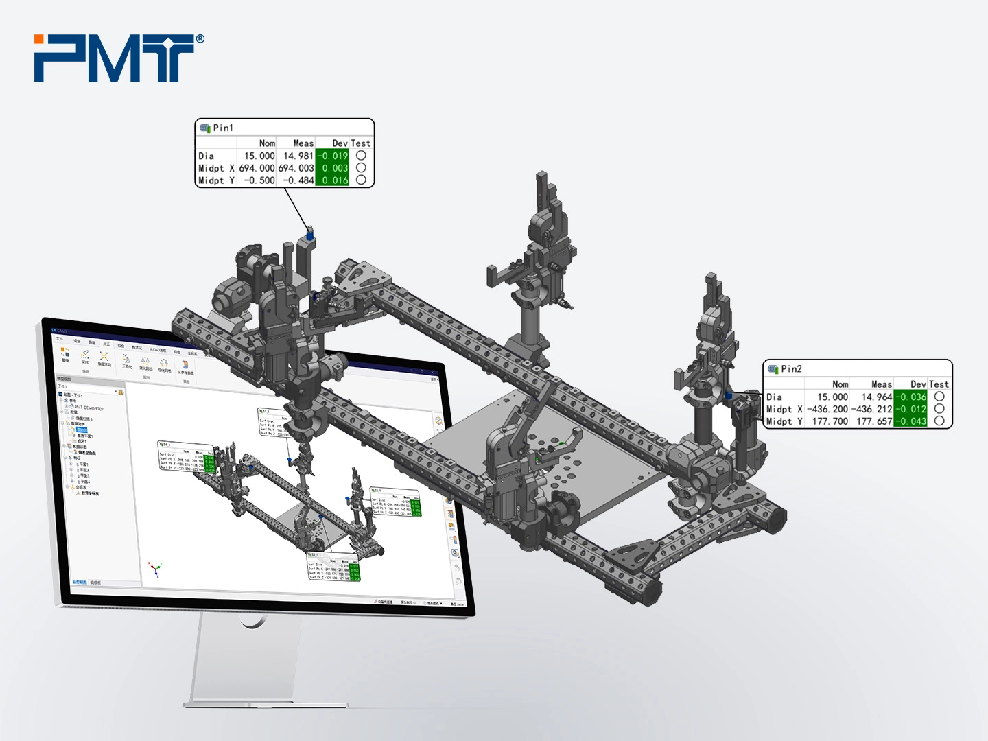
4. Measure gripping unit. The gripping units typically includes cylindrical locating pins, fixing blocks, and chuck blocks. Measure the locating pins using the cylinder feature, and use Build/Inspect to measure the fixing blocks. Chuck blocks are adjusted relative to the blocks and don’t require direct measurement. Compare all measured features with the CAD model to determine necessary adjustments.
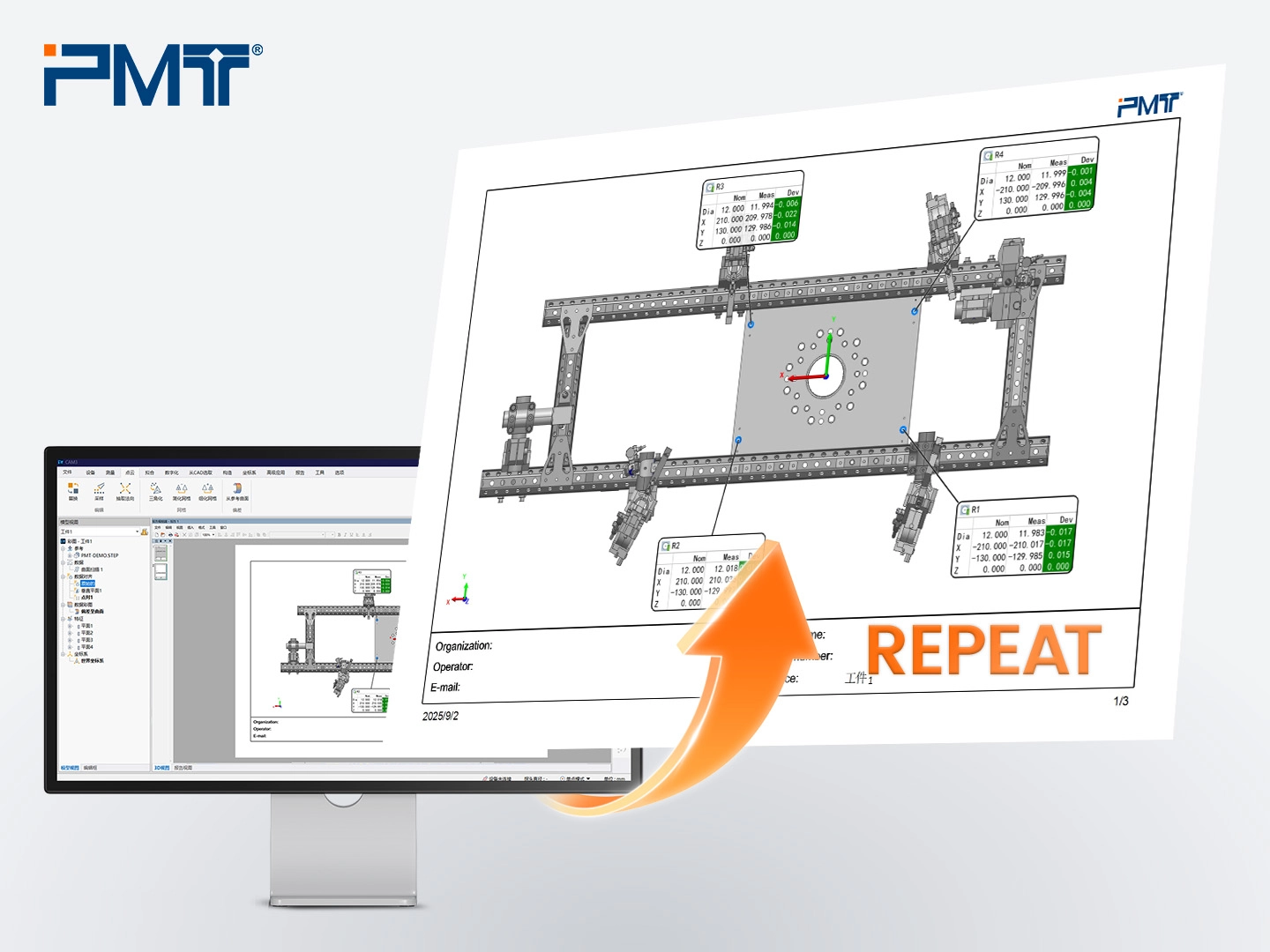
5. Adjust the gripping modules according to the 3D comparison results until all deviations are within tolerance. Then, export the export in PDF format.
B. On-Site Re-Measurement of the Gripper
After the octagonal tube gripper passes initial measurements, it may still undergo slight deformation due to vibrations or external forces during transportation. Therefore, re-measuring the gripper on-site with a portable CMM is essential after installation. This ensures the gripper’s performance and confirms its precision.
The re-measurement process mirrors the initial factory checks, typically requiring only a 3D comparison to verify the gripping unit’s accuracy.
C. Robot Calibration Assistance
Once the gripper’s accuracy is confirmed, robot calibration can be performed on the welding fixtures. First, establish a coordinate system using the gripper’s fixture and define the robot’s movement trajectory. Next, use a portable measuring arm to measure the coordinates of at least four fixed datum holes along the trajectory. Finally, input these values into the robot’s system to complete the calibration.
Customer Feedback
The Turkish customer shared that before purchasing the PMT portable measuring arm, they outsourced most measurement tasks. However, since a recent surge in orders, shorter delivery times, and externally sourced materials made scheduling measurements difficult, which significantly driving up production costs.
Since acquiring the PMT Arm, these issues have been resolved. After just two days of training, the company’s fitters quickly mastered the device. The integrated workflow has eliminated installation errors and significantly reduced costs on outsourced measurements.

Conclusion
Octagonal tube grippers are widely used in the automotive welding and automation industries for their modular design, high strength, easy assembly, and long lifespan. Moreover, the portable coordinate measuring machine ensures high precision, portability, and rapid 3D inspection, making it crucial for both verifying the gripper’s accuracy before shipment and shortening delivery times while reducing costs. Therefore, the measuring arm has become an indispensable tool in the production process of octagonal tube grippers.